Autonomous Car
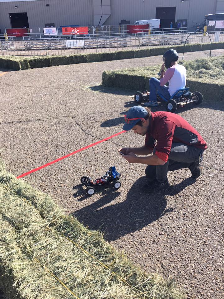
Robotics has been an interest of mine ever since I was a child, but much to my regret my attention was diverted towards video game development for much of my teens and early twenties. However, in my mid twenties my attention was again grabbed by robotics. And thanks to Sparkfun's AVC, I was given a real goal to pursue. Navigating a race course un-aided by local navigational beacons or other such techniques that make navigation much easier. I've made several attempts, and failed many times, but learned a lot along the way.
v1
To start out, I began with an old RC car that I raced as a kid. I fit it with a RaspberryPi model A+ as the brain, a GPS module that the PI could talk to over UART, one of the PI Camera modules and an LSM9DS0 motion sensing board. It was a bit of a shotgun approach in sensor choice, little did I know, but each would present their own challenges. My initial idea was to use the LSM9DS0 to determine heading, the GPS module to determine location, and the camera to detect obstacles. I first started by writing some C programs to interface with the LSM9DS0, had some initially promising results.
In a controlled environment (my house) after writing some code to perform calibration and interface with the servos, I got it to work 'perfectly'. However, I quickly learned in the real world it wasn't that simple. Here's it's first run outside.
In that video, the car was attempting to drive in a straight line, and doing a rather drunken job of it. At that time it had been relying on the magnetometer's readings alone. Which I came to the conclusion must have been interfered with. In that video, I was atop a parking structure, made of concrete that undoubtedly contained rebar and steel structure for reinforcement. So I figured the magnetic fields from those ferrous materials probably were the cause of the regular, wobbly heading.
In response, I spent quite a bit of time working on trying to mitigate the influence of magnetic interference by trying to weight it's measurement by the angular velocity measured by the gyro. Again, I was able to make it work fairly well in a controlled environment, but not so much in reality. I came to find that I was in a constant balancing act between the noise of the gyro and corrupted heading from the magnetometer.
It was around this time that I began noticing the shortcomings of civilian GPS. I was working on a waypointing system that the car could blindly drive to. The waypoints were defined as simple lat-lon coordinates either by driving over a course first, or by setting them from a companion app I had developed to run on my phone. It was at this time that I began to notice the inaccuracy. In this video, the car is trying to seek my phone which is acting as a beacon. While it does follow, it's response is quite sluggish.
It was after doing some research, I discovered that civilian GPS receivers are really only accurate to about 8 meters, which just simply wouldn't cut it on the kind of course that I had planned to navigate. The lanes weren't even that wide. I looked into some possible solutions like averaging readings from several GPS receivers, but ultimately decided that they weren't the right tool for the job. So... I hoped this would be...
I built a rotary encoder module that interfaced with the drivetrain of the car. This module would count wheel rotations, and since I knew how big the wheels are I could determine the distance traveled between each rotation. However, after introducing the rotary encoder, the heading accuracy issues began to rear their ugly heads again. I was attempting to do deadreckoning to allow the car to locate itself.
Deadreckoning is a means of locating yourself in the world by keeping track of the direction you're pointing, and how far you've travelled. Think of a pirate's map, "100 paces to the east, 15 more to the north east and then X marks the spot". Keeping track of paces and direction is effectively what I was attempting to do with direction and wheel rotations. Of course, this too had issues...
Above is a video of it driving an oval, while it does a seemingly good job driving the path, it's too short a distance to be a good measure of performance. What this video is hiding is the accumulation of error that would be fatal to the run over a longer period of time.
The last sensing attempt I made was to use a low-cost range finder paired with my dead reckoning code to detect obstacles ahead, and course correct appropriately. I had planned on achieving this by sweeping the range finder side to side on a turret to generate a plane of distance measurements from which to infer obstacle nearness and position.
This too had a few serious problems. I was using an R/C servo to drive the turret for the range finder, unfortunately (without modification) R/C servos have no feedback mechanism that you can tap into directly so that you can measure its angle. Instead, I had tell the servo to move to the next angle, and wait some time in hopes that it would be at the right position when the measurement is made. I had to strike a balance between bandwidth and scanning accuracy. The other problem that I wasn't counting on at all I didn't experience until race day. That was the fact that the hay boundary of the course seemed to scatter the light from the range finder, such that no readings were reliable in any way...
Time was up, and needless to say the race I had been preparing for didn't go so smoothly, but I learned what didn't work and how to better go about things in the future. On the way back to Michigan from Colorado I wrote this post, to document some of the things I learned.
v2
Taking what I learned from my failures in v1 I sought to give it another try by starting fresh. Here are the major problems I identified and how I was planning to solve them.
Program architecture
The program architecture in v1 was poor. The system was not modular, rather the project compiled as one monolithic executable that did everything. This made containment of bugs, experimentation and expansion of functionality difficult.
What I chose to do instead this time around was Influenced by the UNIX philosophy of having each program do one thing well. Thus split the system into several different programs that perform as few actions as possible. Here is an example of how this turned out.
$ collector -i -a | predictor -r/media/training/0.route
In this example the collector program is run from the command line. collector, as the name implies, collects sensor data, processes it if needed then forwards it to the predictor program which then tries to decided what to do based on the given input.
This pipeline architecture also made debugging much easier, as you could easily visualize the system state by appending the viewer program to the end of the pipeline. Also the separation of concerns in the codebase made the programs much easier to manage.
Dead-reckoning error accumulation
In my post-mortem thoughts about v1, there were a few prospective issues I saw with my approach to dead-reckoning. First was timing. Dead reckoning is basically one continuous integral, and I had written my code such that change in time wasn't factored in properly. Essentially the program controlling the car ran whenever it had a chance. Which meant the time step between each integration step of dead reckoning was random. The way I planned to solve that was by taking advantage of the Raspian scheduler and fixing the deadreckoning code's time-step.
// Use the round-robin real-time scheduler
// with a high priority
struct sched_param sch_par = {
	.sched_priority = 50,
};
assert(sched_setscheduler(0, SCHED_RR, &sch_par) == 0);
The code above tells the linux scheduler to schedule the collector process using the round-robin soft-realtime scheduler.
// Run exclusively on the 4th core
cpu_set_t* pose_cpu = CPU_ALLOC(1);
CPU_SET(3, pose_cpu);
size_t pose_cpu_size = CPU_ALLOC_SIZE(1);
assert(sched_setaffinity(0, pose_cpu_size, pose_cpu) == 0);
Since v2 utilized a RaspberryPi 3 there are 4 cores to utilize, this code forced the OS to run the dead-reckoning thread on the 4th core exclusively to avoid interruption by other processes.
Lastly, I introduced what I termed 'time gating'. The premise being that some code is allowed T time to run, where T should be some interval at least as long as the expected runtime in the worst case. You begin a timer just before the code starts running. When it finishes, t time has passed. You then simply wait T - t longer, then start again. This way your time-step remains fixed for each execution of that code.
Another concession I made was a motion sensor change. I later found an IMU called the BNO055 which wasn't just a gyro, mag, accelerometer combo, but also included a Cortex M0 to perform sensor fusion on the chip itself. I had high hopes that the engineers at Bosch had it figured out better than myself.

Computer vision
Another thing I focused on more heavily was the use of vision to detect obstacles or goals. The designers of the race colored obstacles red, and some goals either green or blue. The color model of the camera I was using YuYv which separates the chroma (color) from the luma (light intensity) of the image. So cuing on simple colors is made much easier, as shading has less affect on the color represented in the frame.
I wrote a simple algorithm that looked at 'good' and 'bad' colors within some tolerance and added up the amount of 'goodness' for each column of the camera frame. Steering toward the least bad region.
I had also been interested in trying to use stereo vision to deduce obstacle distance and location, however I quickly abandoned that approach when I found the camera in the photo above was actually two separate USB cameras. This was a fatal flaw. For stereo vision to work correctly (especially on a moving platform) the left and the right cameras must capture their frames at the same time. Such that the position of a particular pixel lies on the same plane in both frames. The two separate cameras made that impossible.
Machine Learning
One of the stretch goals I had for v2 was to implement an end-to-end machine learning model that took in raw sensor data, and output steering and throttle commands. To do this, I needed some way to record raw PWM signals for the steering servo and the speed controller. I went down a month long rabbit hole of designing, programming and building a device that sits between the RC receiver and the servos. I used the Parallax propeller as the MCU and programmed it in propeller assembly. I called it the PWM-logger

I wrote an i2c slave driver for the logger that allows a companion computer (RaspberryPi, Arduino, etc) to control it's behavior. It could be put into two modes 'echo' and 'no echo'. Echo mode measures the PWM signal for each channel stores the reading in a register and passes it through to the servo. That allows you to drive it remotely like a normal RC car. While you're driving, the companion computer would be recording all the sensor inputs as well as the throttle and steering outputs.

That way a datasets for training, dev, and testing could be created. Unfortunately I didn't get a chance to utilize this work to it's fullest potential before the competition came. Despite that it was a great experience. This was the first time I had prototyped designed and fabricated my own hardware, as well as using an assembly language to solve a real problem.
Results

Despite some serious improvements, v2 still ended in failure. The big problem again ended up being deadreckoning. The BNO055 did produce interference free orientations, but it suffered from some of the same problems that my sensor fusion algorithms did in v1. Namely that the filters I had configured for it were sluggish, but also there were some strange bugs with the BNO's sensor fusion. It's orientation would occasionally 'twitch' and output a massive change, before returning to an orientation much closer to that of the previous time step.
The computer vision approach actually worked for the obstacles that I had calibrated it for, but unfortunately the car rarely made it far enough to take advantage of that win.
v3
Third time is the charm right? This time I didn't feel the need to totally throw away what I had built in the previous version. Much of the architecture was pretty solid, so instead I decided to improve upon it.
Count your losses
The first thing I did was abandon deadreckoning. Deadreckoning is ignorant about surroundings, thus isn't very capable of recovering from a mishap, or collision. Instead I opted to go for a purely vision based approach.
Do one thing well
I took the UNIX philosophy further and split programs up even more. Now invoking the system looks something like this.
$ collector | predictor -f | actuator
I removed the servo and throttle controls from the predictor program and moved them to actuator. In addition to expanding the pipeline, I spent more time on error handling and writing reusable components for the suite of programs.
Seeing clearly
The algorithm I had devised in v2 for steering around colored obstacles worked fairly well itself, the thing that really needed improvement was the algorithm that detected what patches of the image were 'bad' and what ones were 'good'.
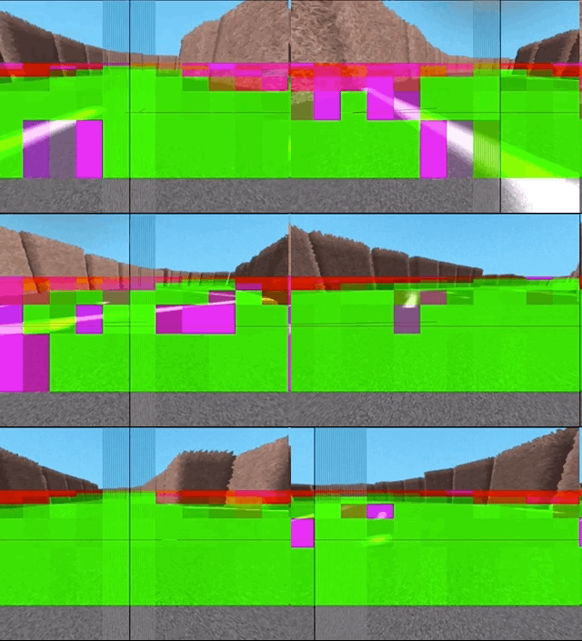
This finally sent me down a machine learning path, but not the end-to-end approach that I originally anticipated. For v3 I fairly successfully trained a fully-connected single layer neural network which classifies small 16x16 pixel patches as either 0: unknown, 1: hay, or 2: asphalt. Unknown and hay both count negatively against the 'goodness' of a column of the image, where asphalt is scored positively. You'll see below in the simulation section, the approach is fairly robust. Even when the classifier isn't confident about what it's looking at.
Simulation

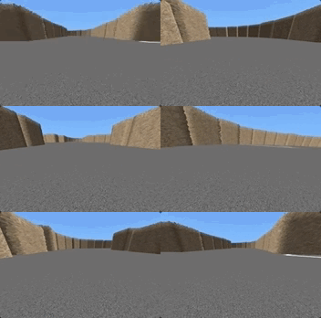
Another game changer that I finally undertook was writing a simulator that could be controlled by the pipeline of programs. The simulator behaves in exactly the same way as the collector program. Outputting an identical payload over stdout to predictor. In turn the simulator also creates a UNIX socket file that actuator can write to, thus controlling the simulated car's actions in the next time-step. The full simulation can be run by creating a pipeline like this.
$ sim | predictor -f | actuator -f | viewer
Which will display a visualization of how predictor is classifying different patches of the image and where it is steering.

So far things are looking good, but there's still more work to be done. Stay tuned!


